File list
Jump to navigation
Jump to search
This special page shows all uploaded files.
| Date | Name | Thumbnail | Size | User | Description | Versions |
|---|---|---|---|---|---|---|
| 17:46, 9 August 2006 | 000004.jpg (file) |  |
5 KB | Andrew S | 1 | |
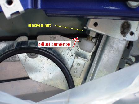
| 18:14, 13 June 2009 | 0011.JPG (file) |  |
24 KB | paulc | leccy window bumpstop | 1 |
| 17:53, 9 August 2006 | 001369.jpg (file) |  |
4 KB | Andrew S | 1 | |
| 21:50, 21 December 2008 | 01accesspanel.jpg (file) |  |
143 KB | moetmoet | 1 | |
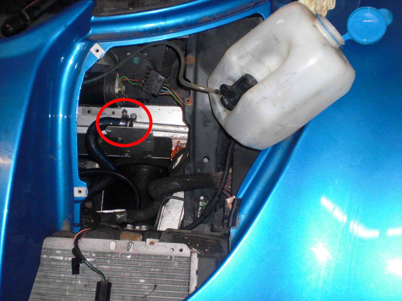
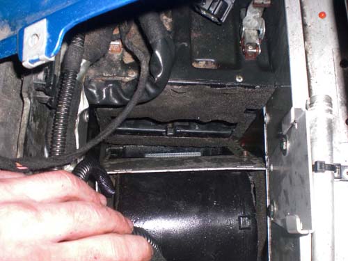
| 22:21, 21 December 2008 | 01resistorchange.jpg (file) |  |
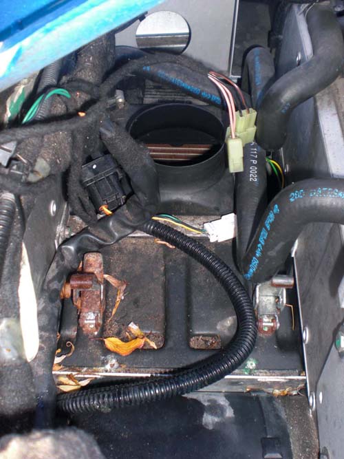
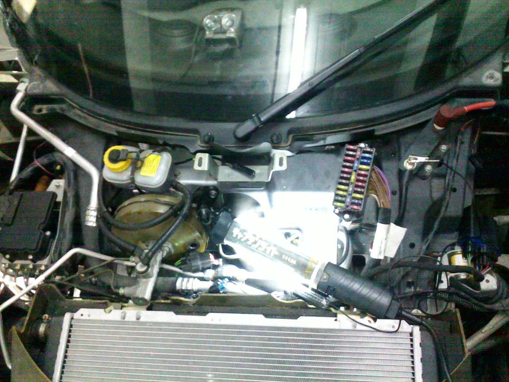
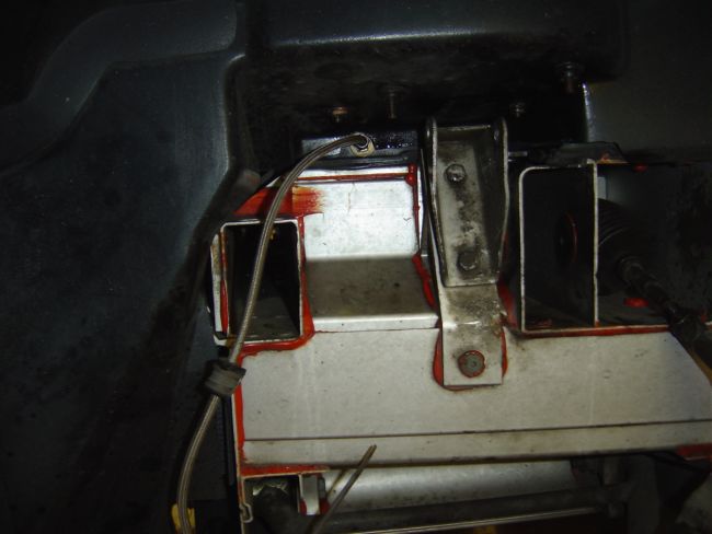
58 KB | moetmoet | Remove access panels and cover panels and washer bottle and heater pipes as circled. There is one pipe each side and a bit of coolant will come out, not a lot. Make sure car isn't running! | 3 |
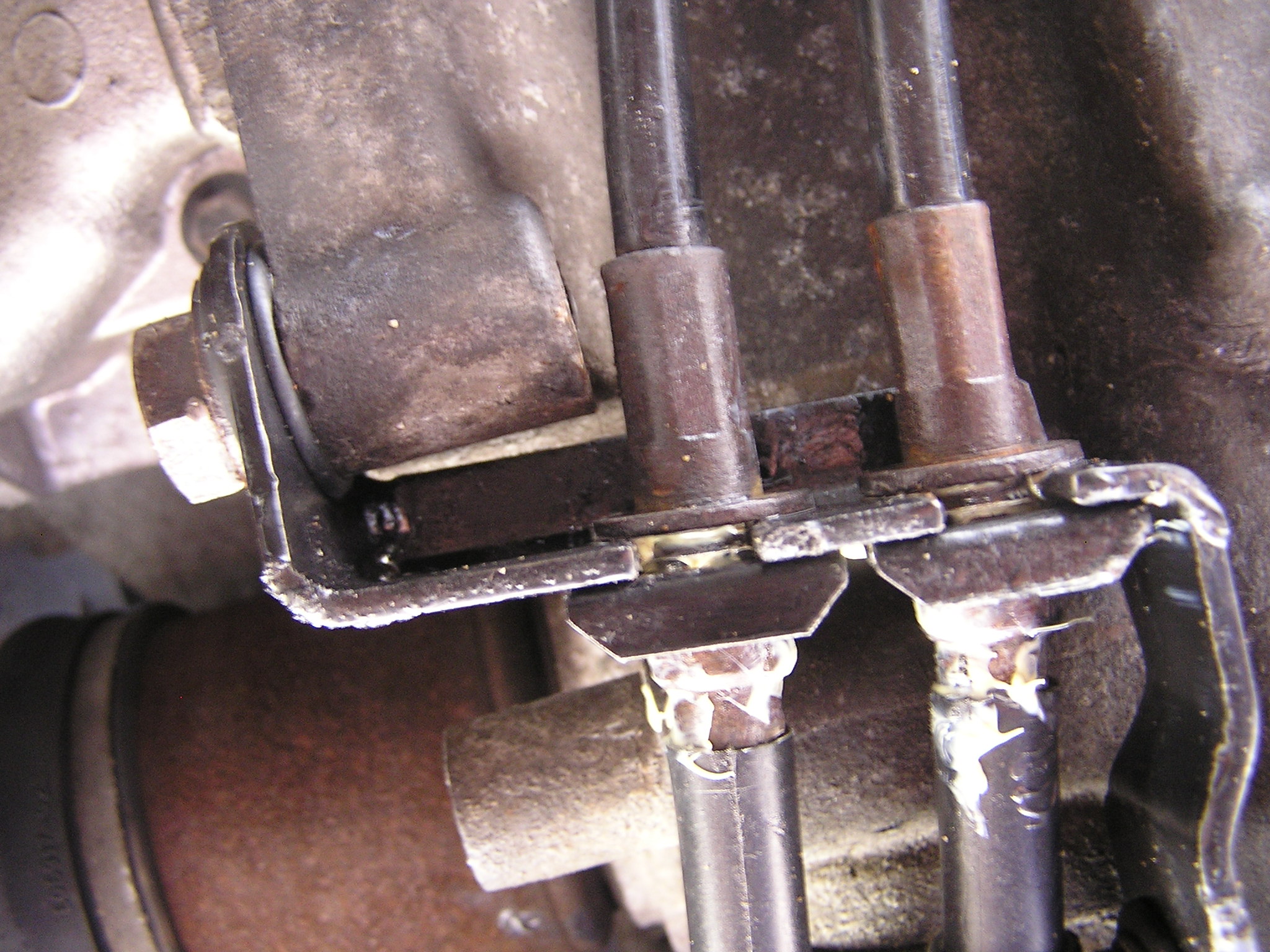
| 22:23, 21 December 2008 | 02resistorchange.jpg (file) |  |
40 KB | moetmoet | remove jubilee clips and pipe, one each side. | 3 |
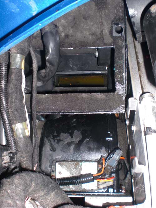
| 22:24, 21 December 2008 | 03resistorchange.jpg (file) |  |
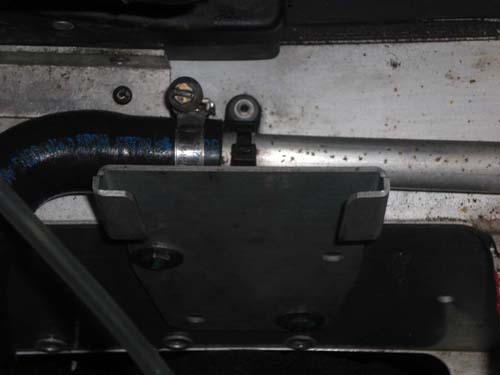
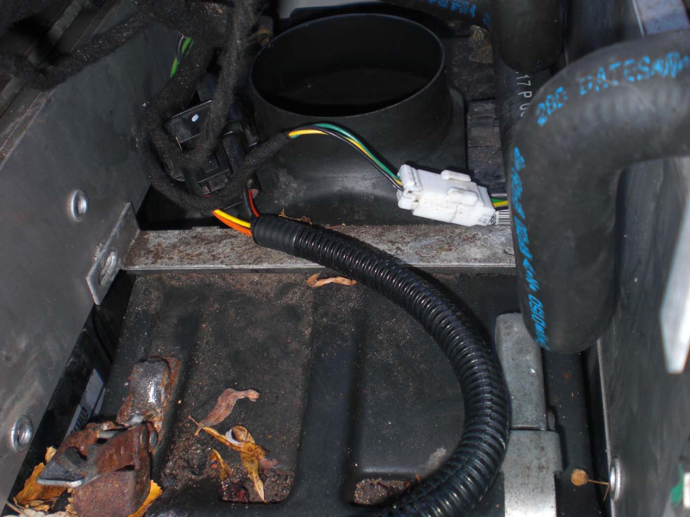
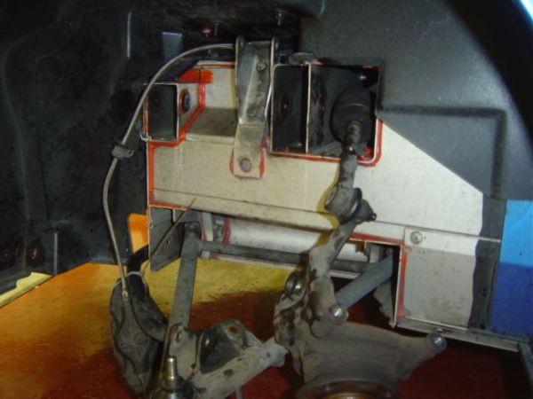
84 KB | moetmoet | As viewed from passenger side front wheel, detach white plug to heater flap, unscrew and remove aluminium bracket and unclip heater from blower. | 2 |
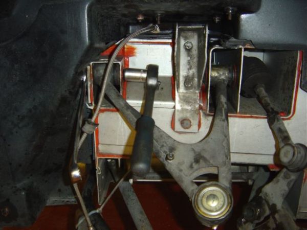
| 10:00, 8 May 2009 | 04052009082.jpg (file) |  |
102 KB | jfedder | Pipework | 1 |
| 10:54, 13 June 2016 | 04resistorchange.jpg (file) |  |
132 KB | AndyKay | Reverted to version as of 21:03, 21 December 2008 (larger photo) | 3 |
| 12:49, 23 March 2017 | 0502.JPG (file) |  |
694 KB | Chopper | 1 | |
| 22:26, 21 December 2008 | 05resistorchange.jpg (file) |  |
61 KB | moetmoet | Pull the fan blower (near passenger side wheel) away from the heater. Stand up heater in the well so the hole is facing up. Very fiddley. | 2 |
| 22:27, 21 December 2008 | 06resistorchange.jpg (file) |  |
92 KB | moetmoet | Heater now standing up. Rotate heater around so that the resistor pack is facing up. Rotate anti-clockwise when looking at the front of the car. Again, very fiddley | 2 |
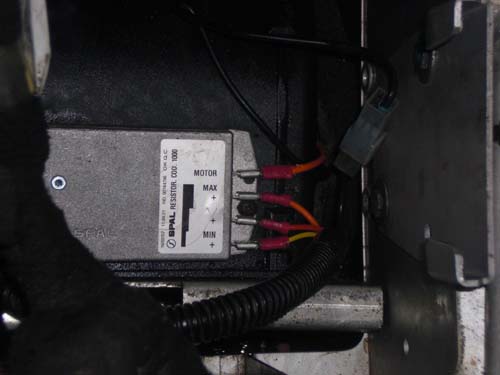
| 22:29, 21 December 2008 | 07resistorchange.jpg (file) |  |
42 KB | moetmoet | resistor pack has two screws. once replaced rewire as shown, will probably need new red spade connectors. | 3 |
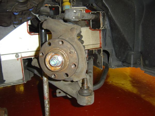
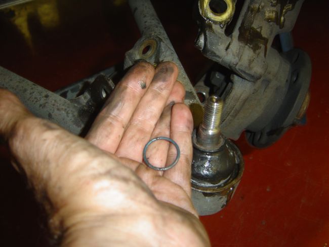
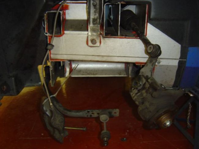
| 09:52, 18 June 2006 | 10. Lower Ball Joint Split From Hub Carrier.JPG (file) |  |
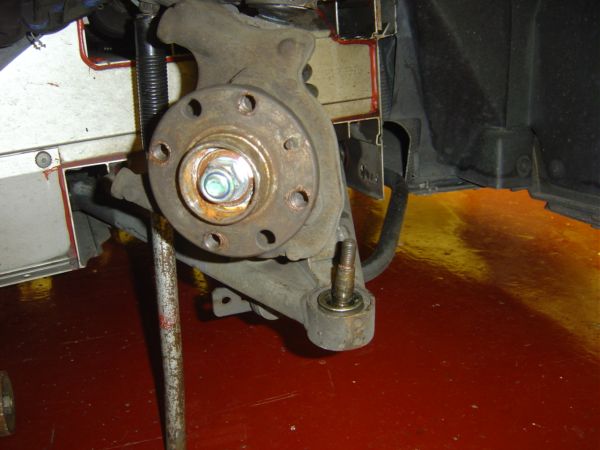
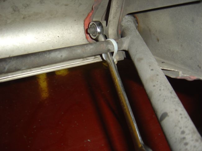
46 KB | Andrew S | Step 9. When the ball joint is split from the hub carrier move carrier out of the way. You could use a trolley jack handle as a prop for the hub carrier under the track rod end bolt. Remove the ball joint rubber dust cover. | 1 |
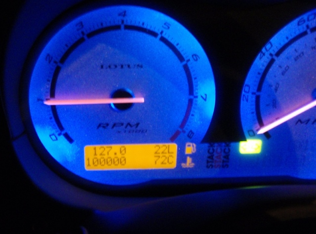
| 21:19, 27 July 2009 | 100000.JPG (file) |  |
101 KB | woody72 | 1 | |
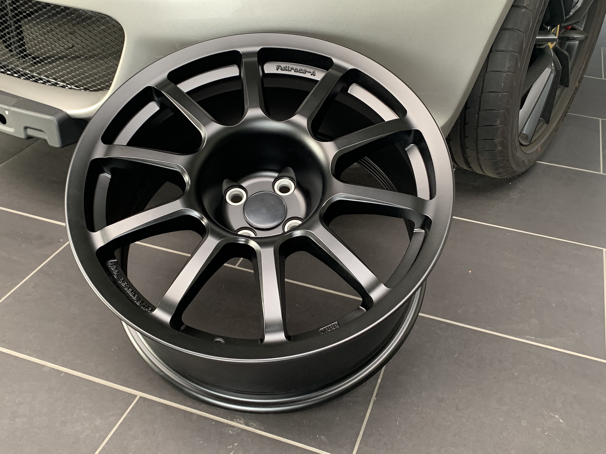
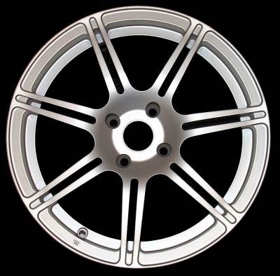
| 18:56, 22 May 2023 | 1012-011-Braid-FR-S1-Felgensatz-Elise-Mk1-1.jpg (file) |  |
841 KB | M!key | 1 | |
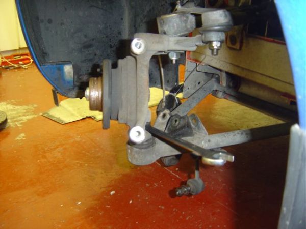
| 22:59, 31 July 2006 | 10 Remove Upper & Lower Ball Joint Nuts.JPG (file) |  |
45 KB | Andrew S | 1 | |
| 09:52, 18 June 2006 | 11. Steering Wheel Set To Full Lock.JPG (file) |  |
45 KB | Andrew S | Step 10. Turn the steering wheel to full lock to move the hub carrier out of the way, so you can fit a ball joint removal tool. | 1 |
| 17:04, 9 August 2006 | 111F1-t.jpg (file) |  |
5 KB | Andrew S | 1 | |
| 17:07, 9 August 2006 | 111RSE2-t.jpg (file) |  |
5 KB | Andrew S | 1 | |
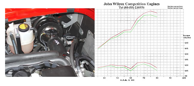
| 14:46, 6 February 2007 | 111R and S2 Exige ITG Maxogen.jpg (file) |  |
51 KB | Andrew S | 1 | |
| 14:43, 6 February 2007 | 111R and S2 Exige ITG Panel Filter.gif (file) |  |
52 KB | Andrew S | 1 | |
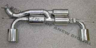
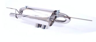
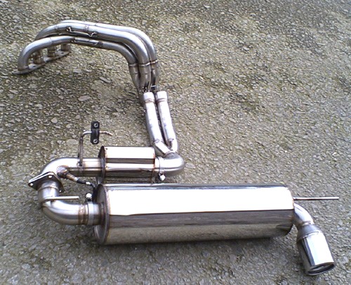
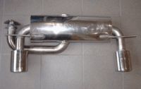
| 20:28, 9 August 2006 | 111S2bularfullperformancesystem.jpg (file) |  |
91 KB | Andrew S | 1 | |
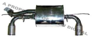
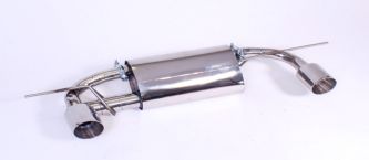
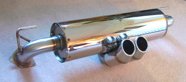
| 20:31, 9 August 2006 | 111Sprotypelargesilencertwin3inchdtm.jpg (file) |  |
136 KB | Andrew S | 1 | |
| 14:50, 15 August 2006 | 111rforge.jpg (file) |  |
24 KB | colbot51 | 1 | |
| 19:06, 13 July 2009 | 111rserv2.JPG (file) |  |
103 KB | Mr Wiki | 1 | |
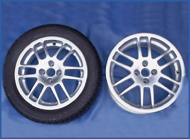
| 14:57, 15 August 2006 | 111rwheel.jpg (file) |  |
9 KB | colbot51 | 1 | |
| 22:59, 31 July 2006 | 11 Remove Both Ball Joints.JPG (file) |  |
46 KB | Andrew S | 1 | |
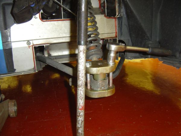
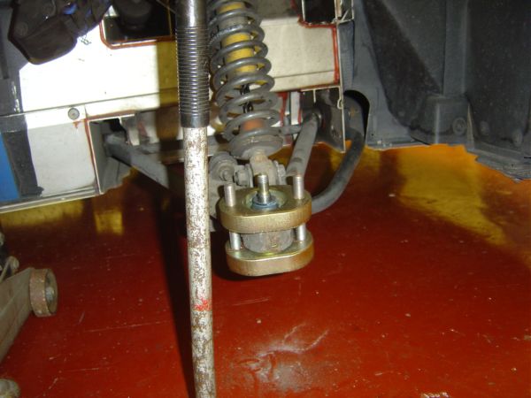
| 09:53, 18 June 2006 | 12. Ball Joint Removal Tool Assembled.JPG (file) |  |
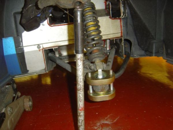
48 KB | Andrew S | Step 11. Assemble the ball joint removal tool and make sure that you coat the bolt threads with plenty of copper grease. This is an Elise Parts ball joint removal tool. | 1 |
| 22:59, 31 July 2006 | 12 Hub Carrier Removed.JPG (file) |  |
50 KB | Andrew S | 1 | |
| 23:27, 30 November 2006 | 12spoke.jpg (file) |  |
52 KB | Mr Wiki | 1 | |
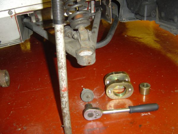
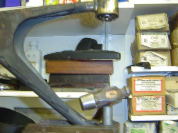
| 09:54, 18 June 2006 | 13. Removing Ball Joint.JPG (file) |  |
46 KB | Andrew S | Step 12. Using a 19mm socket/ratchet , tighten the bolts 2 turns each keeping them even. | 1 |
| 22:59, 31 July 2006 | 13 The spring Clips Usually Come Off the Balljoint Rubber.JPG (file) |  |
42 KB | Andrew S | 1 | |
| 09:54, 18 June 2006 | 14. Ball Joint Removed.JPG (file) |  |
48 KB | Andrew S | Step 13. The ball joint pops out very easily. | 1 |
| 23:00, 31 July 2006 | 14a Remove the Upper Wishbone 1.JPG (file) |  |
46 KB | Andrew S | 2 | |
| 23:01, 31 July 2006 | 14b Remove The Upper Wishbone 2.JPG (file) |  |
49 KB | Andrew S | 1 | |
| 09:55, 18 June 2006 | 15. Greasing New Ball Joint Rubber.JPG (file) |  |
47 KB | Andrew S | Step 14. You may wish to put new ball joints in the freezer for a day or two. This ensures an easy fit into the wishbone. Grease the rubber dust cover so that it does not snag. | 1 |
| 18:57, 11 August 2006 | 154 0.jpg (file) |  |
4 KB | Andrew S | 1 | |
| 19:02, 11 August 2006 | 155 0.jpg (file) |  |
4 KB | Andrew S | 1 | |
| 23:01, 31 July 2006 | 15a Upper Wishbone Removed 1.JPG (file) |  |
40 KB | Andrew S | 1 | |
| 23:02, 31 July 2006 | 15b Upper Wishbone Removed 2.JPG (file) |  |
43 KB | Andrew S | 1 | |
| 23:02, 31 July 2006 | 15c Upper Wishbone.JPG (file) |  |
44 KB | Andrew S | 1 | |
| 09:56, 18 June 2006 | 16. Fitting New Ball Joint.JPG (file) |  |
47 KB | Andrew S | Step 15. Hand fit the new ball joint into the wishbone. It should go in easily if it is frozen as it will be slightly contracted. | 1 |
| 23:03, 31 July 2006 | 16a Remove Lower Wishbone 1.JPG (file) |  |
39 KB | Andrew S | 1 | |
| 23:03, 31 July 2006 | 16b Remove Lower Wishbone 2.JPG (file) |  |
50 KB | Andrew S | 1 | |
| 23:03, 31 July 2006 | 16c Lower Wishbone.JPG (file) |  |
39 KB | Andrew S | 1 | |
| 09:56, 18 June 2006 | 17. Ball Joint Assembly Tool.JPG (file) |  |
44 KB | Andrew S | Step 16. Fit the ball joint assembly tool and hand tighten the bolts making sure everything is evenly spaced. | 1 |
| 23:03, 31 July 2006 | 17 Both Wishbones Removed.JPG (file) |  |
40 KB | Andrew S | 1 | |
| 09:57, 18 June 2006 | 18. Ball Joint Fitted.JPG (file) |  |
46 KB | Andrew S | Step 17. Tighten the bolts two turns at a time until the ball joint is seated. The heat created during fitting will defrost the ball joint. | 1 |
| 23:04, 31 July 2006 | 18a Remove Sleeve from Polybush.JPG (file) |  |
46 KB | Andrew S | 1 |